Blog: Servo Loop Tuning – part1
APPLICATION NOTE: Servo Loop Tuning – practical approach
Direct drive servo actuators have an unquestionable performance capability, the final performance is mostly determined by the servo loop tuning.
Servo motors have the ability to create torque in a linearly predictable fashion and it makes them attractive for use in closed loop systems. Despite the wealth of theoretical material regarding closed loop systems and closed loop control, tuning a PID servo loop continues to be a bit of an art. This application note provides some practical guidelines how to make servo loop tuning a deliberate engineering exercise.
The PID Controller
The PID controller is one of the most used control algorithms in any closed loop system (not just for motion, but also in process control, temperature control…).
The PID controller derives its name from the 3 components that comprise this algorithm:
![]() P: proportional term. This term results in an output signal that is proportional to the process error (difference between desired parameter value – setpoint - and actual)
P: proportional term. This term results in an output signal that is proportional to the process error (difference between desired parameter value – setpoint - and actual)
![]() I: integral term. This term results in an output signal that is the integral (i.e. sum over time) of the process error.
I: integral term. This term results in an output signal that is the integral (i.e. sum over time) of the process error.
![]() D: derivative term. This term results in an output signal that is the derivative of the process error.
D: derivative term. This term results in an output signal that is the derivative of the process error.
In general, these 3 terms act independently from each other and their outputs are summed together to create a single PID output signal.
Other configurations are possible as well. For example, derivative term may act only on the feedback (output) signal, not the error signal, with proportional term in parallel with integral term.
In motion control application process error, described above, is difference between desired and actual motor positions, i.e. position error.
Effect of the PID Terms
Let’s take a look at a practical tuning exercise and take a closer look at the real effect of the various gains. Digital servo drive and motor with encoder feedback will be used to illustrate the effects of the various gains, as well as to provide some practical guidelines.
One of the best ways to evaluate PID tuning, is to look at the step response of a system.
In order to make sure that the system does not saturate and to avoid strong nonlinearities, small signal excitation and its response will be used. In addition to looking at the position response, torque will also be observed, as a measure of “how hard we are driving”.
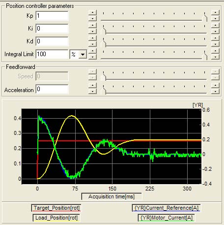
Below is a picture of the response with just a small proportional gain value. The integral and derivative gains are set to zero:
.jpg)
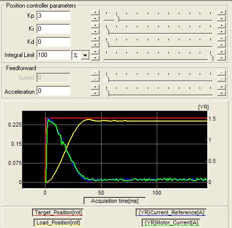
The red curve is the step reference. The yellow line is position feedback. The blue and green curves are reference and actual current respectively (which are proportional to torque).
As seen above, the response is very sluggish. After increasing the proportional gain a few times, we can get to the following result:

This system has almost no friction and exhibits large overshoot, even with small gains.
If friction is added to the system, damping characteristics will improve, but larger gains will be required. Addition of the friction will introduce small steady state error, not allowing the system to reach final target position.

This should always be the first step in servo loop tuning. Start with just proportional gain and look at the response.
If the system has a tendency to overshoot quickly, even with small gain, likely the friction is low.
If more gain is required to get any response, and the response is slow, the system has considerable friction. This determines the next step.
Comment
Rating Bad Good


