LINEAR ACTUATORS


Click HERE to enter new IntelLiDrives website www.intellidrives.com


Linear motion - performance comparison

  Linear Motor Technologies
Stepping Motors Servo Motors

Single axis

Linear Stepper

Dual axes

Planar system

Single axis

servo motor

XY table

positioning type open/closed loop open/closed loop closed loop closed loop
max. stroke [in] 144 80 144 12
speed [in/sec] 60 80 200 100
acceleration [g] 2 2 10 10
peak force [lb] 2-50 2-30 20-2000 200
cont. force [lb] 2-50 2-30 10-500 100
drives

stepper drives

Linear ServoStep

stepper drives

Linear ServoStep

brushless

 amplifier

brushless

 amplifier


repeatability [μm] 2.5 2.5 0.5 0.25
accuracy [μm/m 25 25 10 5
bearing

roller or

air bearing

air bearing linear bearing linear bearing
 
Linear motors - Types and construction


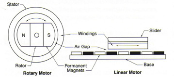
Linear Servo Motors are frameless permanent magnet three phase brush-less servo motors. They are, fundamentally, rotary motors that are rolled out flat. In linear motors the rotor rolled out to become a magnet track. The rotary stator became linear motor forcer coil assembly.  It is typical, in linear applications, for magnet track to be stationary and to have a moving forcer assembly, due to their relative sizes and masses. In short stroke applications, their positions can be reversed.


The are three types of linear motors available from IntelLiDrives:


Iron core single magnet track motors have coils wound on silicon laminations to maximize generated thrust forces. They also have attraction forces between iron forcer and magnets in the track, which is beneficial to preload air bearings, for example. With mechanical linear guides this attraction force preload the bearings. Iron core motors also exhibit so called cogging force caused by the tendency of the forcer poles to aligned themselves with magnet poles.

IntelLiDrives linear motors are designed to reduce both attraction and cogging forces that allow them to be used in high precision constant velocity applications.


Iron core dual magnet track motors have dual magnet track to balance magnetic attraction forces between forcer and magnet track. Using them with mechanical linear guides produces quite and smooth linear actuators without concerns for bearing lifetime.


Iron-less motors (also called slot-less) have no iron or slots. These motors have zero cogging and attraction forces and coils are very light.  They are applied when very low friction and extreme low speed velocity smoothness is required. To maximize thrust forces dual magnet tracks are used. These motors can also be supplied with single magnet track.

 
Linear actuator construction
 

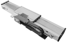
IntelLiDrives has introduced a new packaged linear motor slide that can be used as a direct replacement for mechanical linear motion systems. Linear motors have achieved a remarkable penetration into engineering applications previously dominated by ball and roller screws. Understanding that many users of screw technology perceive linear motors to be complicated by comparison, IntelLiDrives has packaged its range of LC-Series brush-less linear motors in easy "ready to use" linear actuator configurations. All that the user has to do is configure a linear actuator package in much the same way as they would to integrate a mechanical screw.


linear actuator
   

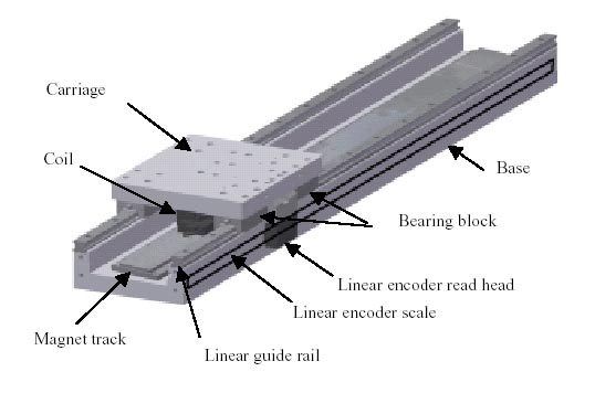
Each packaged linear actuator system consists of a linear motor, bearing, encoder and cable management system. The smallest model is an extremely compact unit for its output, measuring just 90mm x 60mm in cross section. As with all linear motors, the linear actuator packages are virtually maintenance free, with no moving parts in contact with each other. The motors offer a high output, with a continuous force range of 80 N -600N, with 250N - 1300N peak, and a high acceleration rate. There is low cogging (0.5% of peak force) and no backlash, with a range of sizes available to suit user requirements.


Each linear actuator package is completed with a high quality linear bearing, fitted together with a contact-less linear encoder and  proprietary cable management system. The packaged linear motors can be driven using standard IntelLiDrives brush-less servo amplifiers and controllers to provide a completely integrated system.

 
Linear motors - Glossary Of Terms
 

Continuous Force (Fc)

The force produced by continuous current (Ic), with coil is attached to an adequate heatsink as specified. At continuous force motor temperature equal to the maximum temperature rating of the forcer


Peak Force (Fp)

The force produced by peak current (Ip) for duration of 1 second


Motor Force Constant (Kf)

This is a figure of merit for motor efficiency. Defines how much force is produced per unit of current. It is the ratio of the continuous force Fc to the continuous current


Max Power Dissipation (Pc)

The continuous power losses of the motor with the continuous current Ic applied to the coil, when motor reached max temperature rating of the forcer with the ambient temperature at 20°C


Maximum Coil Temperature (Tmax)

The maximum rated temperature of the coil  120°C. However, good practice is to limit the continuous current to no more than 80% of the rated continuous current


Back EMF Constant p-p (Ke)

The ratio between the back emf voltage in volt peak to the motor speed


Peak Current (Ip)

The magnitude of the 3 phase sinusoidal currents that need to be applied to the motor to develop the motor peak force (Fp).


Continuous Current (Ic)

The continuous current corresponding to the continuous Force


Resistance l-l @ 20°C

This is the cold coil resistance measured phase to phase (line to line) at 20°C


Inductance l-l (L)

This is the coil inductance measured phase to phase (line to line)


Magnetic Attraction (Fm)

The magnetic attraction force exerted between the coil assembly and its magnet assembly, measured at the nominal air gap.


Forcer Mass (Mc)

The mass of the coil including the standard cable length. For air cooled and water cooled motors it also includes the mass of the cooling tube or cooling plate


Magnetic Track Mass (Mm)

The mass of the magnetic track per unit of length.
 
Linear Actuators motion profile formulas


Linear motor system design considerations
 

To achieve the highest performance in positioning systems, the entire linear actuator structure must be optimized to result in the highest possible natural frequency, and the entire servo system design must be optimized to achieve the highest possible closed loop bandwidth. The designer of a linear motor actuator should therefore be aware of various design considerations, which are somewhat different than traditional servo system practices.

  • Very high magnetic attraction (up to 10 times drive force) can exist between the motor parts. This requires careful handling of the magnetic plates, before and during installation, proper installation tools, and design for ease of disassembly in the field

  • Linear bearings must be selected to support both the moving load and the magnetic attraction force. Desirable bearing characteristics include high stiffness (for increased natural frequency) and low friction. Because linear motors can provide higher velocities, the speed and acceleration limitations of the bearings need to be considered

  • Metal chips must be kept outside the magnet assembly by proper seals and bellows. This is needed to prevent machine chips from penetrating the small air gap between the motor parts

  • The motor air gap must be maintained within specified tolerance for proper motor functioning. The machine bearings and linear guide-way must be of sufficient precision to maintain the air gap

  • Brush-less linear motors typically have moving cables. Provision must be provided in the machine to carry the cables. Motors with cooled coils will also have moving air or liquid coolant lines

  • If a liquid cooled motor is selected, the coolant should include a rust inhibitor additive. The over-temperature  thermistor should be connected to a safety interlock circuit in the amplifier control system to prevent overheating.

  • When used in a vertical application, linear motors typically require a brake mechanism to prevent the load from dropping in the event of a power interruption

  • The forcer should be mounted as close as possible to the center of mass of the moving load. The position feedback linear encoder should be mounted as close as possible to the working point of the machine. If the forcerand feedback are far apart, the machine structure and bearings must be of sufficient stiffness to minimize dynamic deflections of the structure

  • Cables should be made in a twisted pair configuration, shielded and grounded properly to the machine base, servo amplifier and motor to reduce RFI. Cables should be selected for proper flex life at the designed bend radius

  • Brush-less motors require commutation for proper operation. IntelLiDrives amplifiers support sinusiodal commutation method for motor optimal performance


Accuracy vs Resolution

A common misconception is that the resolution of the device must also be its accuracy. For example, if a digital readout displays to four decimal places (0.0001), then it must also be accurate to that same value. That is usually not the case.  Although high resolution is a prerequisite for high accuracy, it does not guarantee it. Consider the two graduated scales:

Both scales have 15 graduations over equal arcs; therefore, both have identical resolutions of 1/15th arc. For arc A the resolution increments are equal; however, for arc B the resolution increments are obviously not the same.  That difference, scale accuracy, is a component of position accuracy, and while both examples have the same resolution, each will provide very different results. 

Accuracy is the difference between the actual position and the position measured by a reference measurement device. Stage accuracy is influenced by the feedback mechanism (linear encoder, rotary encoder, drive mechanism (ball screw, lead screw, linear/torque motor), and straightness/parallelism/run-out of the bearing guide-way. IntelLiDrives uses laser interferometers (for linear axes) and autocollimators (for rotary stages) as a reference measurement tools.


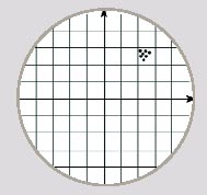
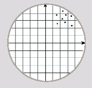
Repeatability is defined as the range of positions attained when the system is repeatedly commanded to one location under identical conditions. Uni-directional repeatability is measured by approaching the point from one direction, and ignores the effects of backlash or hysteresis within the system. Bi-directional repeatability measures the ability to return to the point from both directions.


Resolution - The smallest possible movement of a system. Also known as step size, resolution is determined by the feedback device and capabilities of the motion system.


Low Accuracy

High Repeatability


Low Accuracy

Low Repeatability


High Accuracy

High Repeatability


Click HERE to enter new IntelLiDrives website www.intellidrives.com